Daisy Chain test die are suitable in a wide variety of process related applications, such as life cycle testing, drop testing, measuring CTE (Coefficient of Thermal Expansion), selecting the correct amount of solder paste, evaluation of solder paste stencils, checking for voids caused during reflow, underfill experiments, etc.
The use of standard components (without Daisy Chain) might be sufficient when demonstrating and evaluating mounting machines (a.k.a. pick and place machines). Rudimentary applications such as machine maintenance, calibration and acceptance testing require only simple dummy packages, without Daisy Chain.
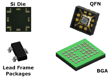
However, for true research and optimizing the assembly process, Daisy Chain is required. TopLine recommends Daisy Chain devices with silicon die for the most meaningful results.
Critical applications involving environmental life cycle testing require daisy chain packages with silicon die. The Daisy Chain permits electrical continuity testing, while the silicon die replicates the thermal mass of a "live" device.
Daisy Chain is made by stitching gold bonding wire between pairs of bonding pads on the lead frame. BGA and CSP Daisy Chain is usually made with copper traces between pairs of ball pads on the substrate.
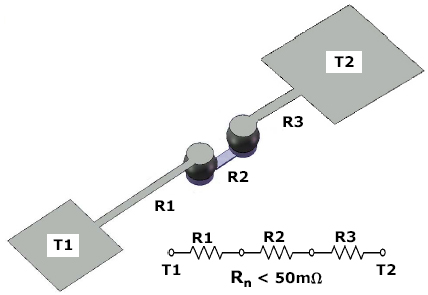
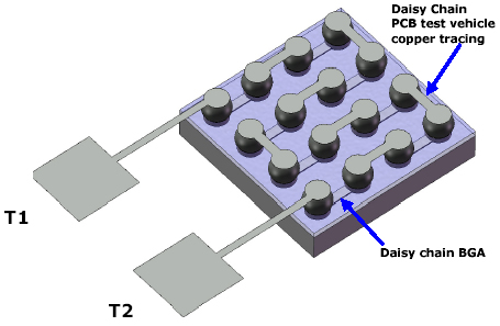
In a Daisy Chain circuit, pin 1 is connected to pin 2 within the device. Pin 3 is connected to pin 4. Pin 5 is connected to pin 6, and so forth until the last pin "N". On the PCB test vehicle board, copper traces connect landing pads pin 2 to pin 3, pin 4 to pin 5, and pin 6 until the last pad.
Electrical continuity is made between the PC board and the DUT (device under test) after soldering. A short circuit is measured using an ohmmeter from the board's from test point T1 to test point "T2".
Solder joint reliability is verified by vibrating, dropping testing and temperature cycling using JEDEC, IPC and Mil specifications (e.g.: -55oC to +125oC in a humidity chamber) until a failure occurs. A "failure" means the Daisy Chain circuit goes from a "short" (≈ 0Ω) to an "open" circuit (∞ Ω). The assembly and solder joint is forensically analyzed to determine the cause of failure. Test devices with daisy chain and silicon die are an economical way to study why failures occur and how to improve the assembly process.
BGA, CSP and flip chip test die with Daisy Chain are used in underfil experiments. Daisy Chain devices are mounted on a test vehicle board, underfilled and then temperature cycled to a point of failure. The results are observed using an ohmmeter to record short circuits (Pass) and open circuits (Failures). Dispensing and encapsulation evaluations also use Daisy Chain components.
Scrap components or live components do not have Daisy Chain. It is impossible to make simple Pass/Fail tests with live components. It is best to use Daisy Chain components for such evaluations.
Major companies such as Intel, IBM, Honeywell, Hewlett Packard, Cisco, Flextronics, Celestica, Sanmina-SCI, Jabil, Boeing, Northrop Grumman, Lockheed and others understand the benefits of using Daisy Chain components for defining and refining assembly processes.
Daisy chain test die offer significant benefits for learning and improving assembly processes.
 |
"Pass" condition occurs when short circuit (≈ 0Ω) is measured between T1 ~ T2.
"Failure" occurs when an open circuit is measured (∞ Ω) between T1 ~ T2. |
 |
| |
| |
| TopLine offers a huge variety of Daisy Chain devices. |
 |
| |