| |
Animated FEA Strain Comparison
Solder Columns vs Solder Ball |
 |
 |
 |
 |
 |
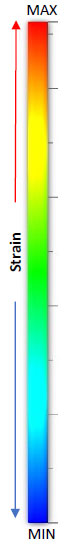
Strain
Scale |
Solder Ball
Core Sn63/Pb37
Size Ø 0.5mm (20mil) |
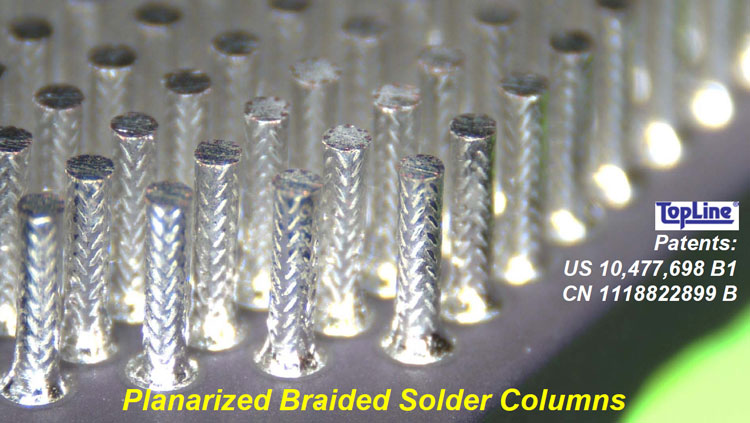
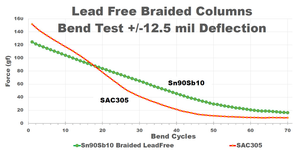
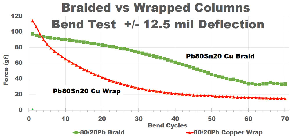
Braided Column
Core Pb80/Sn20
Size Ø 0.5 x 2.2mm |
Cu Wrapped Column
Core Pb80/Sn20
Size Ø 0.5 x 2.2mm |
Plain Column
Core Pb90/Sn10
Size Ø 0.5 x 2.2mm |
| FEA models: View the above animated FEA models of solder ball and columns above as they bend and contort under increasing strain. Darker blue color indicates less strain. Lighter colors (green, yellow, orange) indicate areas with more strain. Braided columns remain darker blue under stress conditions. Solder balls and Plain Columns exhibit the most strain. |
| Why Strain Matters: Solder balls and solder columns mechanically and electrically connect the IC chip to the PC Board. Prolonged periods of thermal cycling under harsh conditions will eventually cause the ball or column to break. After a connection breaks, the electrical signal stops and the system will stop performing. |
| What causes Strain: The biggest culprit is CTE (Coefficient of Thermal Expansion) mismatch. CTE mismatch occurs when mounting an IC Chip package onto an FR4 PC Board and then heating and cooling the system. CTE mismatch is especially pronounced with ceramic packages, but even large organic IC packages experience CTE mismatch. |
| Amount of stress: The larger the IC chip, the more strain occurs. IC chips that operates with repeated temperature swings (cycling the temperature from hot to cold and back to hot) can cause deflection of the solder balls (or columns) greater than 150um (6 mils). That may not seem detrimental, but repeated bending back and forth even a small amount will eventally cause the electrical and thermal impedances to increase, eventually causing balls and columns to fatigue and catastrophically crack. |
| Improving Reliability: Think of solder columns as palm trees bending in the wind without breaking. Under harsh operating conditions, solder columns can withstand more strain without breaking, thus increasing electrical and mechanical reliability. |